The Goal:
Collect efficient design and build tips for transformers for use in an EFHW antennas that can be used with full legal limit power between 1.8Mhz and 30Mhz without having heat issues.
The Problem:
Here is where QRP and QRO meet to fight a common problem.
- Losses = heat = bad. The efficiency of every part and piece needs to be considered.
- Primary winding count differences for all bands 160m and 10m.
- Many different sources (listed below) have many unique tips for various power levels, and after experimenting I’ve found a combination of advice to work best.
Current Designs Results:
- 80m-10m design, and 160m-20m design.
- Typical efficiency > 93% with one minimum efficiency dip to 90% somewhere in the operating range. More on this later.
- Using 800w from my AL80-A amp, I’ve run a half hour of FT8 at 800w on 160m, separately on 80m, separately on 40m at 800w without melting the 1.5″ of snow off the transformer. I put the same amount of snow in my hand and it melted much faster than a high duty cycle!
- Using 1kW I’ve called entire HF nets and conducted long rag chews without melting the 1.5″ of snow off the transformer.
- WebSDR shows good signal form and consistent power output during use.
- Good reports from contacts, QSOs, nets across the bands.
- Minor tuning differences for use on SSB vs digital modes.
- I’m looking for local hams with larger amplifiers to test it further, and other hams to try the build and compare results.
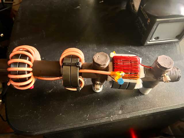
Current design:
<Morgan: remember to insert picture or video of 160m-20m>
Why are there two designs?
I haven’t found a single design that covers 160m-10m. Efficiency goes down quickly at the edges of designs I have. I use two designs which differ in their turn counts to get low losses at the edges, one for 160m-20m and another for 80m-10m. I think the 80m-10m is quite decent for mobile work and I think I can save the 160m stuff for home.
The gap in the secondary coils is optional, and often not needed for the 80m-10m design. When winding the 160m-20m design then concentrating space in the gap to keep the outer part of the turns together helps improve consistency of performance.
Common materials
- 3x 240-52 toroids for transformer
- Epoxy (or super glue) to hold toroids together
- 12awg magnet wire primary turns (2x for 80m-10m, 3x for 160m-20m)
- 14awg magnet wire for additional secondary turns (count depends on design)
- TDK capacitors (150pf, 220pf. Capacity depends on design option)
- Kapton tape for enamel protection
- Zip ties to help turns stay put while building
- Solder to join the primary secondary coils, connect coax.
- Scotch 2228 and Super 33 to help coax feed be water tight.
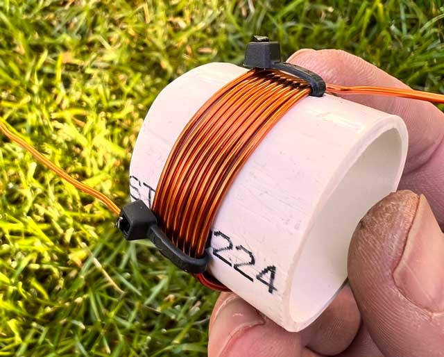
- 1/2″ PVC pipe, elbows, T’s, caps for an open mount.
- Fiberglass cloth for an insulator between PVC and transformer.
Common Parameters
- Autotransformer style tests as more efficient than any twisted or parallel design. I’m showing my design as of now, and will post content on the comparisons in the future.
- <coming soon: links of my own and others comparing efficiency different styles>
- Tight winding style with thick wire tests as more efficient than any spaced or crossover design. I’m showing my design as of now, and will post content on the comparisons in the future.
- <coming soon: link of my own tests and others comparing efficiency of different winding styles>
- Quality capacitors are more efficient than cheap ebay or no-name amazon capacitors.
- <coming soon: link of others comparing efficiency of ebay capacitors vs TDK>
- Able to be mounted outdoors, exposed to the elements.
Build Steps:
Core prep
Three 240-52 cores are used as they can handle more power on HF than type 43 material. I’ve yet to get my design hot when using, however type 52 has a higher curie point than type 43 and also has less losses in this kind of design.
- Clean your toroid surfaces with alcohol and allow to dry. We want a clean surface for bonding.
- I use epoxy since it’s rated for higher temperatures than super glue.
- Clean your stacked toroids again with alcohol, then use a little kapton tape on the inner and outer toroid edges to avoid damage to the magnet wire coating.
- I’m not concerned about shorting across the toroid, rather I’m concerned about arcing between turns in which wire enamel was damaged along a shared edge of the toroids.
- Lastly, since this design may be exposed to the elements I’m concerned about damaged wire coating allowing water to corrode the coils.
- Apply polyimide kapton tape to the edges so as to protect the delicate enameled wire.
- Worried about the tape being a thermal insulator? We’re just using a little on the abrasive edges of the toroids so there’s still plenty of bare toroid exposed. See the pictures and videos.
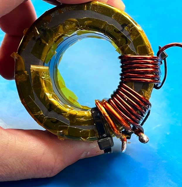
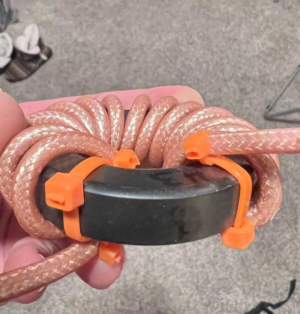
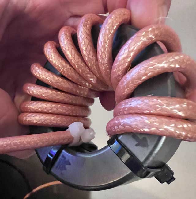
Windings
This is hugely controversial because of some really great theory and testing by some really smart guys working with slightly different materials and slightly different goals. Here’s what I’ve found from my testing in this QRO design:
Use large gauge wire to help mitigate ohmic losses, proximity effect, and leakage inductance.
The primary coil has the most current so it’s best to use at least 12awg wire. The secondary coil has less current and more voltage, but larger gauge wire here give you better coupling as well dealing with proximity effect. I use 14awg. If you use something bigger then be prepared to deal with limited space inside the core and having to space your windings at some point. If you do need to space the wires then take a look at my video/pics about the spacing in groups to maintain great performance.
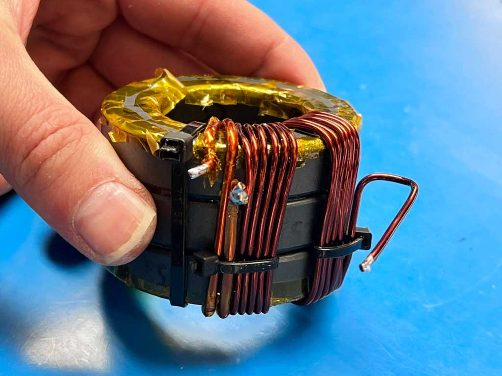
Use a tight winding pattern, the tighter the better. Don’t worry about proximity effect or inter-winding capacitance or core saturation at this point. I’m not necessarily going to dive into theory here, I’m more of an empirical kinda guy and this design has tested very well and stable. Every test design I’ve ever done with spaced windings has resulted in an inferior build for this QRO design. All inner parts of turns should touch, and the outer parts should be as close as possible, or spaced in groups.
Forget about a cross over. Not to the other side of the toroid, and not across or under the primaries. It’s just not necessary in this build and the benefits don’t outweigh the detriments with regards to performance in this build.
- You need about 4.5″ of wire per turn, but wind with some extra length so you can more easily work with it. Want 11 turns? 11*4.5=49.5″, so I’d cut it for 55″. If you’re not good at making closely conforming turns then add a couple more inches and work on conforming.
- Make the windings as tight as possible. Take the time to work with the wire, make good bends around the corners, and straight runs in/around the toroid, and try to have no gap between the toroids and the wire. Be careful to avoid nicks and damage to the magnet wire coating.
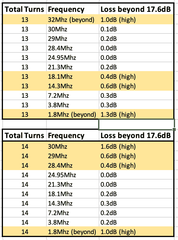
- For 80M-10M use 2 primary turns, 11 additional secondary turns for a total of 13 turns. That one less winding than expected trades off efficiency at 20m for 10m, or visa versa. 13 total turns favors 10m, and 14 turns favors 20m. I chose 10m.
- For 160M-10M use 3 primary turns, 19 additional secondary turns for a total of 21 turns
- Physically secure and then solder the secondary turns to the primary turns.
Shunt Capacitor
The capacitor improves efficiency and extends the usable range of the transformer. In these designs I am using a single capacitor appropriate for the frequency range of the design, however there may be some benefits to “double tuning” the transformer through the use of parallel/series combinations to further extend the range.
Use high quality capacitors from a distributor like mouser and avoid any cheap capacitors from ebay. This has a dramatic effect on the efficiency of the design and is almost as important as the capacitance used.
I mount the capacitor pointing away from the transformer so as to minimize unwanted coupling issues.
- For 80M-10M, 150pf. 120pf is too little but close, 180pf is too much but close.
- For 160M-20M, use 180pf or 220pf. They’re pretty similar.
Testing
You may test with either the resister method or the back-to-back method. The results have been fairly close to one another but there are good arguments for using one over the other, especially if you’re trying to quantify precisely how good something is. If you’re just tweaking things like turn spacing or different capacitors to notice a difference then the resister method is a little easier and will let you see the differences.
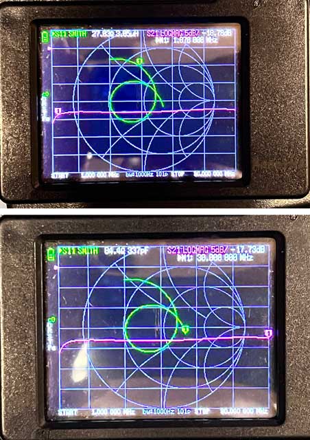
I tested with my nanovna, for better or for worse, and calibrated my nanovna at the ends of my leads, and my leads are soldered to the transformer for testing. Please realize that this method has an error margin larger than other testing methods, but when testing other designs using this exact setup then it’s pretty clear this model is more efficient than other designs.
My pics and video here are with the resister method with a 2.825k load so with the equation:
dB loss = 10log(R+50/50)
my baseline is -17.6db. The pics and videos here are using the 80M-10M design and you can see how efficiency quickly dives at the edges of this range.
Pro tip: Be sure to remove your hands from the transformer and step away when testing so you don’t couple to it and alter your results. Also, test your transformer when it is elevated from your workbench table top so there isn’t coupling there either.
Chokes
Coming soon. Heads up, Jim Brown K9YC has a design I just can’t beat. I use 2 stacks of 2x cores each. One stack is type 31 material, the other stack is type 43 material. Combining materials in the same stack lead to combining the worst traits of both, whereas using a single material for each stack and then putting them in series (shown below in the mounting section) gave me the best of both worlds for choking impedance at the low and high ends of HF.
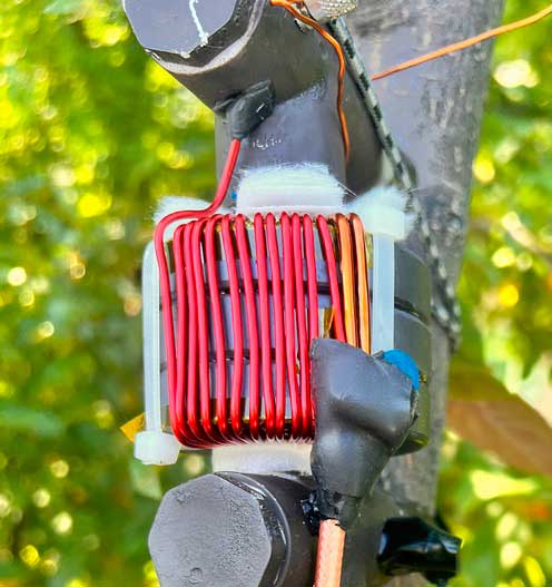
Mounting
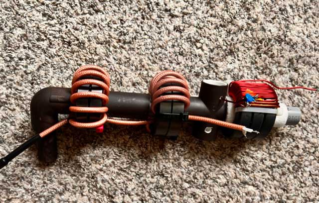
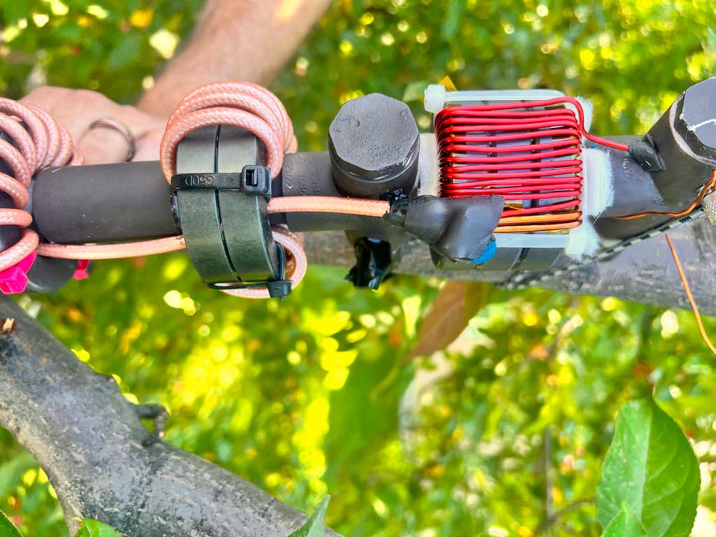
Coming soon. Heads up, I use an open air design that is resilient in the face of water, ice, and sunlight. Make the mount, add a choke, solder your coax on, seal with 2228 and super 33, and you’re ready to go.
Element Tuning
Coming soon. Heads up, I cut it so the first harmonic on where I want it, then I use a compensation coil to lift the higher frequencies into proper bands, then a capacitor half way through the entire element to raise the fundamental.
Additional Resources:
Here are a list of resources I’ve used, and people’s whose ideas I’ve experimented with. You’ll find my design has snippets from each of them. These are the giants upon whose shoulders I’m standing.
- KN5L https://www.kn5l.net/kn5lEfhwUnun/ (winding design, interesting cross overs, leakage inductance, inter-winding capacitance)
- Owen Duffy https://www.owenduffy.net/ (efficiency and a whole lot more)
- Evil Lair Electronics https://www.youtube.com/@evil_lair_electronics (efficiency, motivation, and encouragement, element tuning w/coil, and materials)
- Steve Ellington N4LQ https://www.youtube.com/@n4lq (design elements, materials, and production techniques)
- Colin Summers MM0OPX https://www.youtube.com/@MM0OPXAmateurRadio (testing testing testing. This guy’s material put a bug in me)
- Waters Stanton https://www.youtube.com/@watersstanton (element tuning w/coil and capacitor)
- Smokin’ Ape https://www.youtube.com/@TheSmokinApe (what hasn’t this guy tested?)
- Gary Rondeau https://squashpractice.com (winding design, leakage inductance, inter-winding capacitance, the necessity for kapton tape)
- Jim Brown K9YC http://audiosystemsgroup.com/ (his chokes worked better for me than Mack/John Sevick designs)
- W2FMI Jerry Sevick and W5IFS Raymond Mack (transmission line transformers)
- W5NBC (introduction to efficiency through magloops and metal tape)
- Numerous facebook groups and Elmers who said EFHW was horribly inefficient. They *were* right. It was, until now.